
September 9, 2026
Flashforge Creator 5 Pro Top Cover Hinges: My DIY Mod

Watch the video on YouTube. Opens in a new tab.
I designed hinges for the Creator 5 Pro top cover before I had even done a print on that machine. So was this a problem that desperately needed solving? Honestly, I have no idea. Taking the cover off seemed annoying, I wanted it to hinge, and I had fun figuring out how to make that happen.
The result lets me open the top for filament access or servicing without taking the whole cover away. The video follows the design as I made it up along the way. Below is the full installation with the same photos and steps from my model page.
Files and illustrated installation: download the hinge mod and follow my step-by-step MakerWorld instructions. Use that page for the current parts, hardware lengths, and assembly photos before starting. The video includes prototype parts that differ from the uploaded design.
Before you start
This is an invasive modification. You will drill eight 3 mm holes into the acrylic cover and replace two factory screws on the side of the machine with longer ones. If you are not comfortable with that, I recommend not attempting it.
I do not take responsibility for damage during installation or use. If I find a problem, or somebody reports one, I will try to update the model with a fix. If that is not possible, I will remove it to prevent further problems. Check the linked MakerWorld page for the current version before printing.
The hinges use existing mounting points on one side because I did not want to drill the printer frame or rely on adhesives. Somebody may well come up with a more elegant solution. I simply wanted to give this idea a try.
Material and print settings
I do not recommend PLA or PETG for these parts. The PLA in the video was only a prototype. I replaced every part with PA612-CF. Use a rigid, temperature-resistant filament suited to this job.
Keep the parts in their supplied print orientation. I arranged them to avoid weak layer-line orientations and tested the supplied strength settings. Do not reduce the walls, top or bottom layers, or infill percentage. Increasing them is fine; a different infill pattern should also be fine. Only minimal supports are needed.
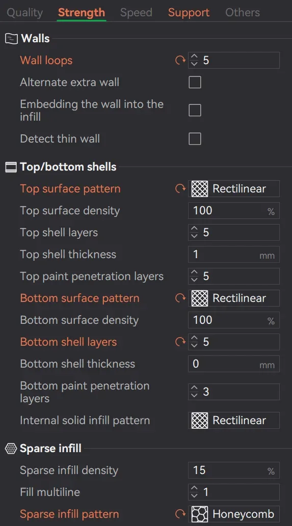
The holes are intentionally tight to reduce play. In most cases, you will work the screws through gradually so they thread the holes slightly. If your printer struggles with dimensional accuracy, you can carefully open the printed holes with a 3 mm drill bit.
Parts and hardware
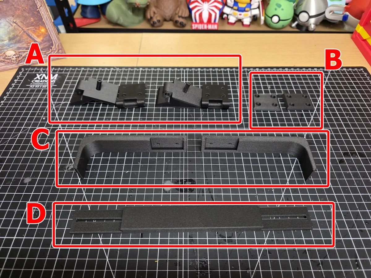
The printed set has two hinge assemblies, each made of two parts (A), two backplates (B), two mirrored side reinforcements (C), and one middle reinforcement (D).
| Position | Hardware for both sides |
|---|---|
| Hinge pivots | 2 × M3×40 mm screws and 2 M3 nuts |
| Printer mounting points | 2 × M3×45 mm screws and 2 M3 nuts, as I used; M3×40 mm is the shorter alternative |
| Upper backplate holes | 4 × M3×20 mm screws |
| Lower backplate holes | 4 × M3×10 mm screws for a flush fit |
| Backplate fasteners | 8 M3 nuts across the upper and lower screws |
Those quantities cover the complete two-hinge assembly shown here. The 45 mm mounting screws let me add nuts inside the printer. With lower backplate screws, extra length affects how far the lid opens: 12 mm protrudes slightly, and longer screws reduce the opening angle further.
Step 1: assemble the hinges
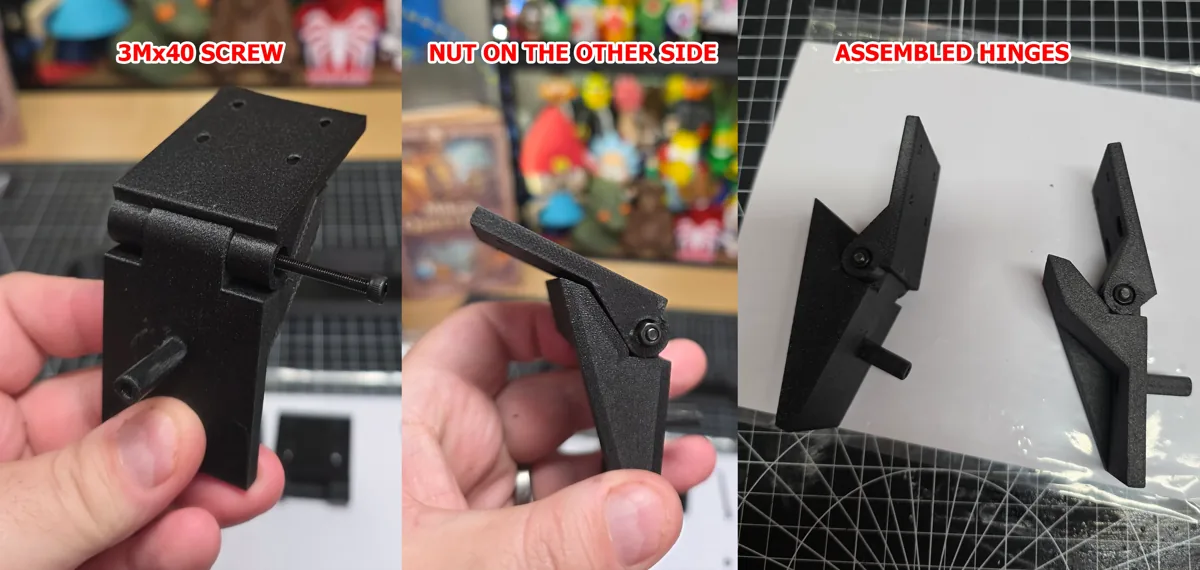
Fit the two halves of each hinge together. Each one takes an M3×40 mm screw and an M3 nut. Refer to the photos for the orientation. The fit is tight by design.
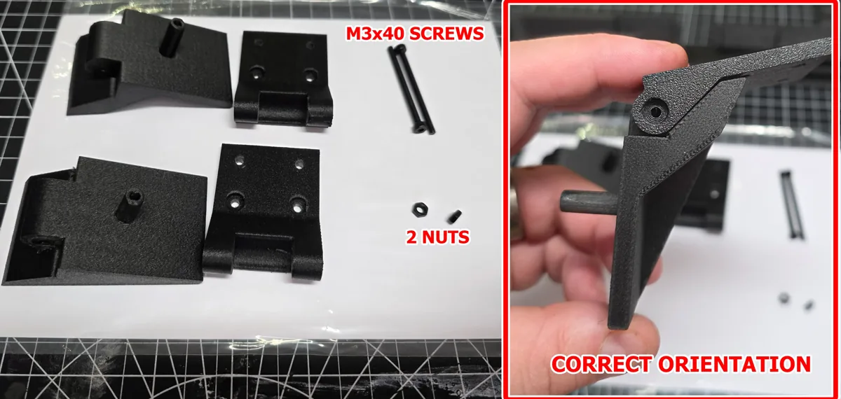
The screw can enter from either direction, as long as it passes completely through and is secured with the nut.
Step 2: fit the hinges to the printer
Remove the two factory screws from the toolhead communication assembly, at the positions shown below.
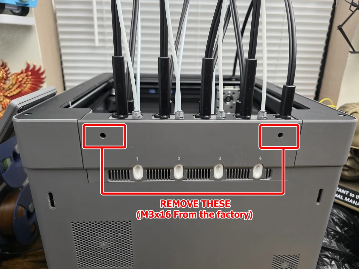
Push the hinge locating pins into those holes and make sure they seat completely. You may need to twist or wiggle them slightly. If a pin is excessively tight, lightly sand or shave it rather than forcing it.
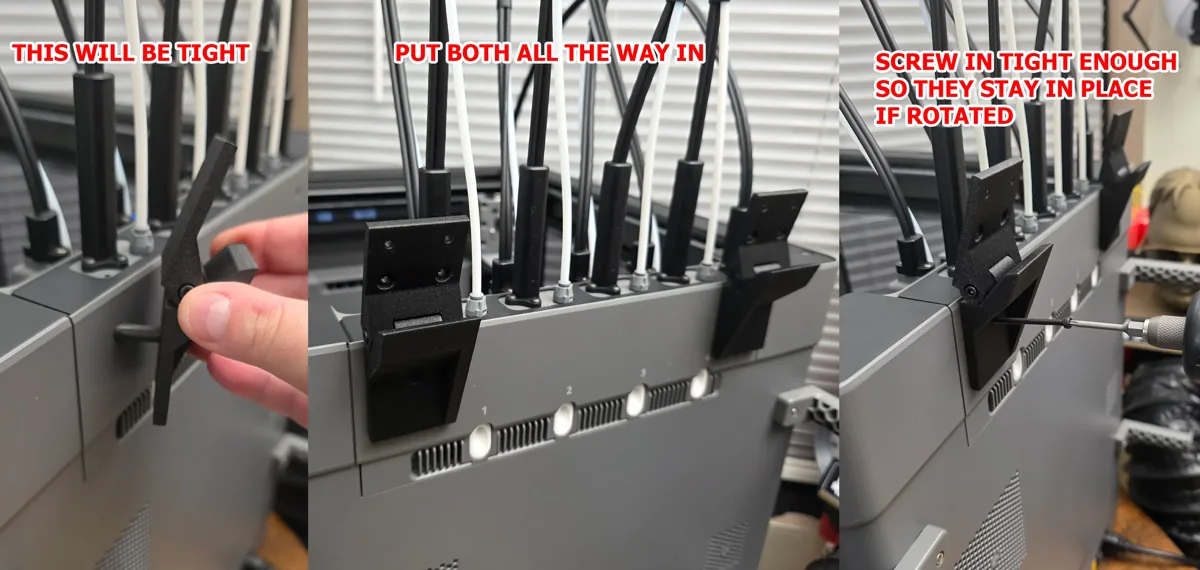
Secure each hinge, but leave the screws a little loose for alignment. On my machine, M3×40 mm was almost flush on the inside. I used M3×45 mm screws and added nuts inside instead.
Step 3: align the cover and mark the holes
Put the cover back on the printer. It needs to sit straight, flush, and as far toward the hinges as possible. Flip the hinges up against it, then fit the mirrored side reinforcements. Each reinforcement only fits on its intended side.
Rotate the hinges slightly left or right until the reinforcements sit flush against the cover walls and corners. Lightly tighten the mounting screws if the hinges move too freely. Repeat on the other side.
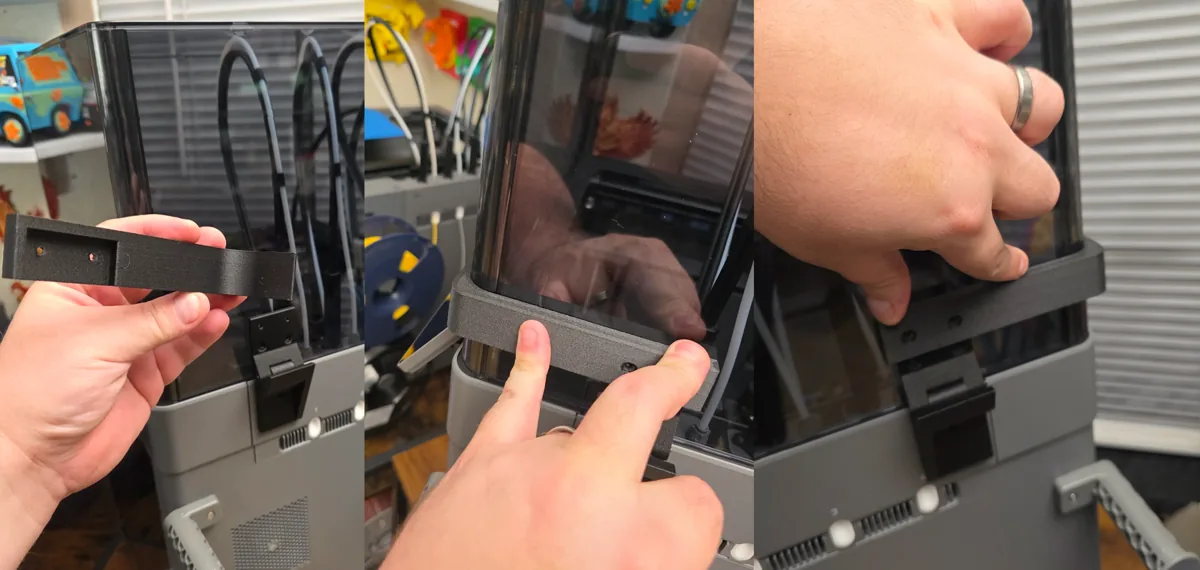
When everything is aligned, mark all eight drilling locations through the hinge holes. Take your time. Up to this point, you can still put everything back without drilling the cover.
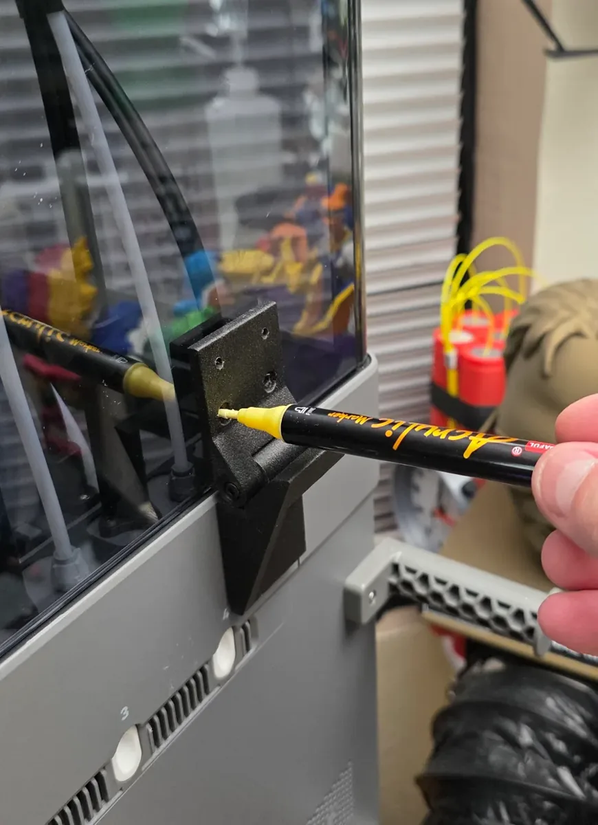
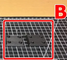
Before drilling, check your marks with the square backplate (B). Huge thanks to @UncleJessy for testing and suggesting this extra check.
Step 4: drill the acrylic
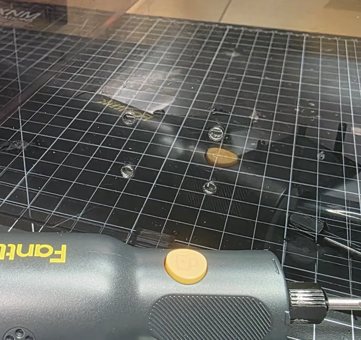
Remove the cover and place it on a supported work surface. With a sharp 3 mm bit suitable for acrylic, drill all eight marked holes very slowly to avoid cracking it. Remove the burrs and debris afterward. Keep the drilling away from the printer.
Step 5: install the backplates
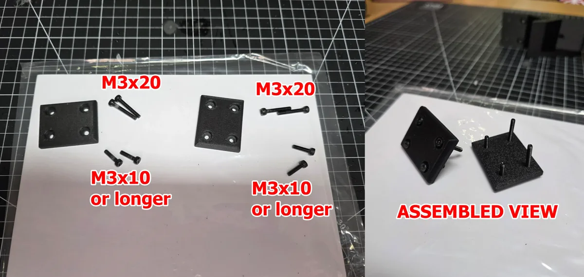
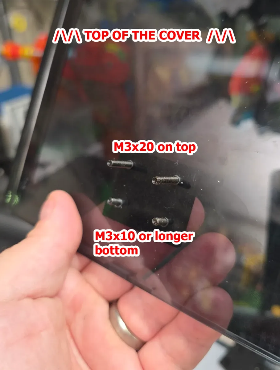
Put M3×20 mm screws in the two top holes of each backplate and M3×10 mm screws in the two bottom holes. The shorter lower screws give a flush fit and the larger opening angle. M3×12 mm or longer can work if you prefer a smaller opening angle.
Insert the screws through the acrylic from inside the cover. The backplate should sit completely flush against the inside wall. Repeat on the opposite side.
Step 6: attach the hinges to the cover
Remove the hinges from the printer again. Slide them onto the screws protruding through the acrylic from the backplates. Because the holes are tight, you may need to turn each screw gradually with a screwdriver instead of pushing the hinge straight on.
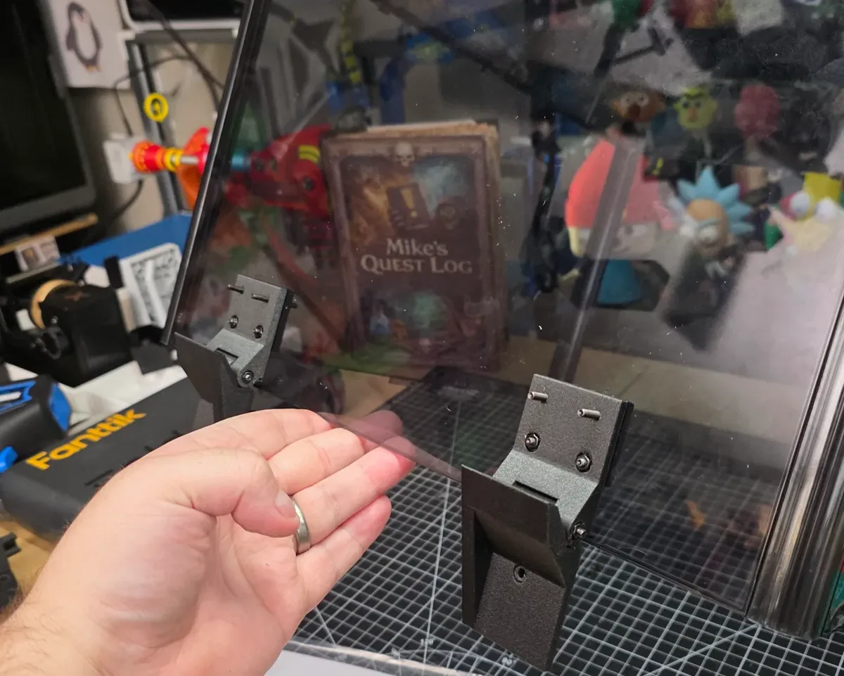
Step 7: add the reinforcements
Secure the lower four screws with nuts, two per hinge.
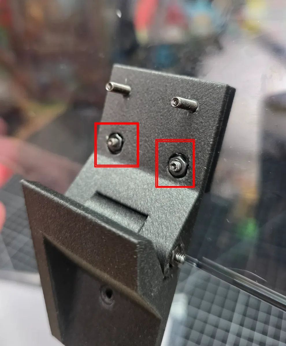
Fit both side reinforcements, then place the middle reinforcement across the top. On the final assembly the reinforced sections face inward, keeping them out of the way of larger spools.
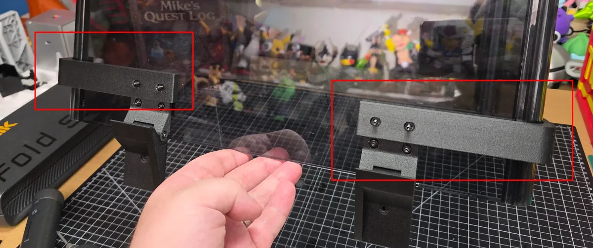
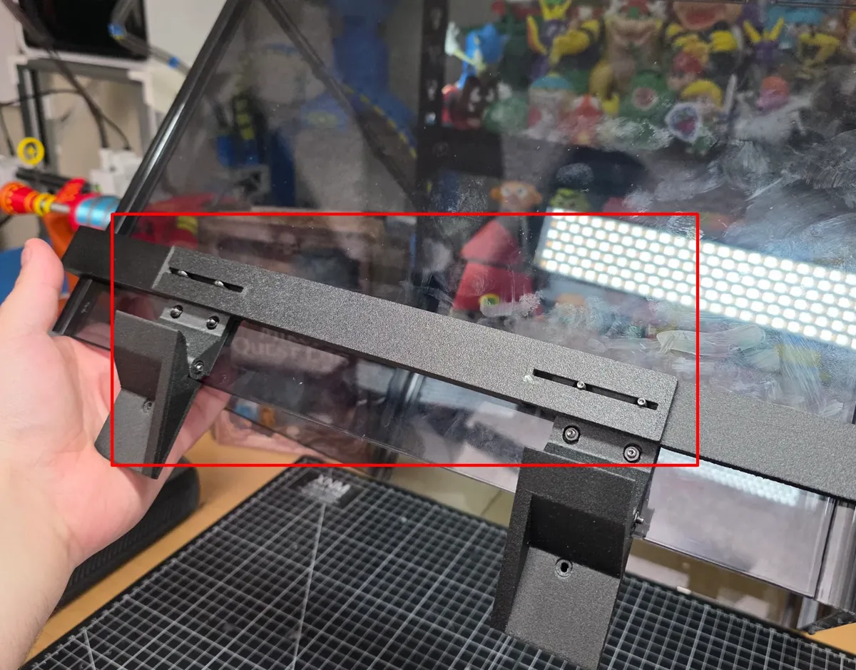
Secure the remaining four screws with nuts and tighten the assembly firmly, without overtightening against the acrylic. The middle brace made a big difference to the rigidity on mine.
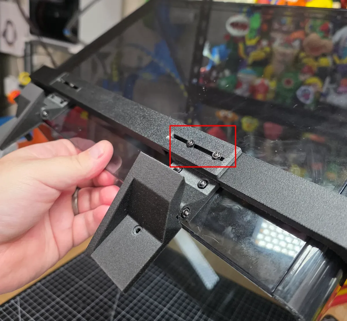
Step 8: reinstall the cover assembly
Flip the hinges outward and guide the two locating pins back into the printer mounting holes. A second person supporting the cover makes this much easier.
Once the pins are fully seated, close the cover and reinstall the side screws from Step 2. Tighten everything, then gently check the opening and closing movement.
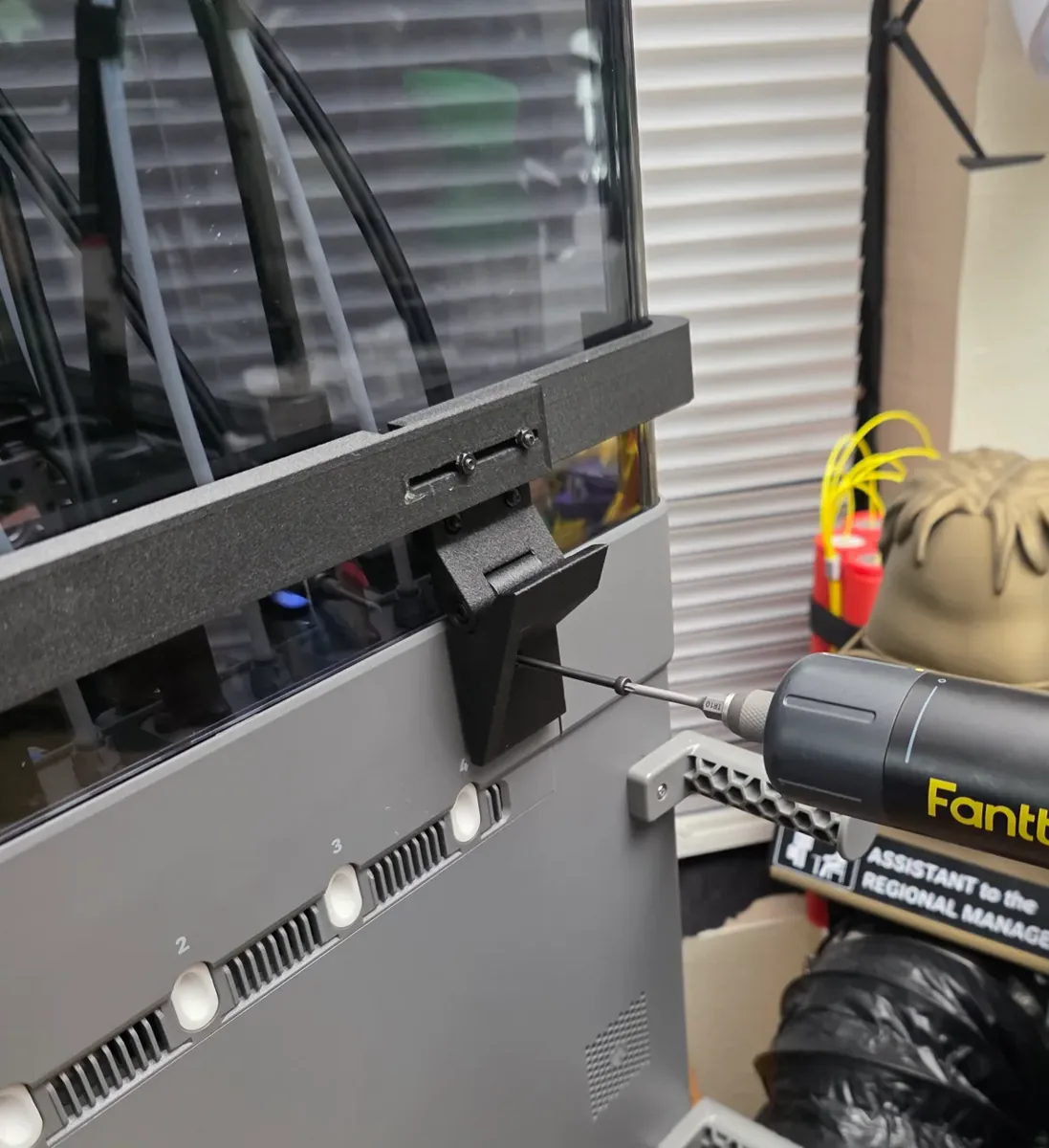
How I would use it
I would open the cover when I need access, then close it when I am done. I would not slam it back, put extra weight on it, or leave it hanging open all the time. I do not know how the acrylic will hold up to that stress over the long term, and I am not interested in finding out the hard way.
That is really all I wanted from this mod: easier access, no extra holes in the printer frame, and a solution I enjoyed designing. It is not something everybody needs. If the original cover does not bother you, there is nothing wrong with leaving it alone.
I also show my toolhead cable strain relief and the updated rear-purge bucket near the end of the video. Those are separate projects. Start with the hinge model page if you want to build this one, and check my other uploads from there.
If you are still looking at the printer itself, the Flashforge store link supports the channel, and DEAL30C5 gives $30 off on that website. You can also check it on Amazon. The code is for the direct store.


